


This is a quick robot to build to try play with H Bridges and to fulfill my life long desire to build a robot to follow a line drawn on the floor. O.K., it isn't a life long desire, but I was disappointed when my first line follower didn't work out.
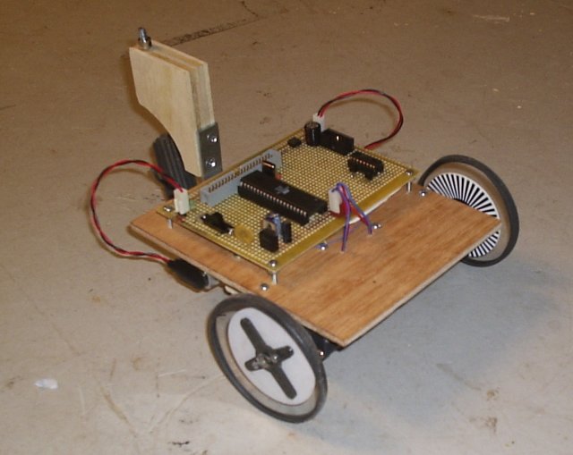
 4 Oct 2005 - Platform with no Electronics (top). (Larger image) |
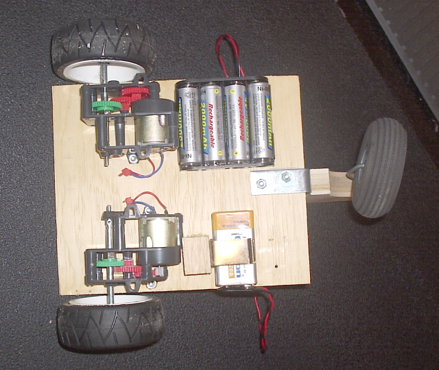 6 Oct 2005 - The bottom of the base platform showing the motors, gearboxes, and battery mounts. (Larger image) |
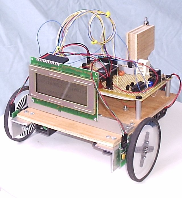
 14 Oct 2005 - Added homemade lexan wheels I made with my Dremel and wheel encoders. (Larger image) |
I used a piece of Luan board as a base, and mounted 2 Tamiya "High Efficiency" High Power gearbox motors. I chose the 68:1 gear ratio. The first drive wheels I chose were some R/C car wheels with really hip low profile tires. The follower wheel is one of those foam R/C Aircraft foam tires. I used wire I bought to install a suspended ceiling tile wire for the axle of the follower wheel. That stuff is really useful (think really thick bailing wire).
All of the wheels I initially chose have issues. The racing wheels don't get much traction, and it is important that the wheels slip as little as possible for autonomous navigation. The rear wheel really isn't swivelling that much. It kind of drags and stays pointed in one direction. I think it might be affecting the direction of the robot when moving.
I built some new 3 inch drive wheels out of polycarbonate (lexan) using my dremel and a circle cutting attachment. I used rubber bands for tires. They aren't as "cool" looking, but they seem to work better. I may need to make them with a larger diameter later.
To control the motors, I'm using a TI SN75441 H Bridge I/C that I bought from Glitchbuster. That is much easier than building your own!
To begin with, I prototyped the motor controller using the Wright Hobbies DevBoard-M32, which is a neat little mounting board for an ATMEGA32. Since that is the only ATMEGA32 I have, I'll probably switch to another Atmel chip when it goes 'live'.
I looked into my drawer full of microprocessors and pulled out an Atmel ATMEGA162. This chip has lots of pins (40), 16K of FLASH, 1K SRAM, and enoufh other junk. One of its distinguishing features is that it has 2 USART perephrials, so I can have a serial port for debugging and another serial port to use I2C (Two wire protocol.)
If you look closely at the image of the robot, you may notice something missing from the controller board. The resistors are mounted on the bottom of the board. I used surface mount componets because I wanted to try them out. They are a little bit difficult to work with, but the advantage of them being so tiny is that they really save a lot of space!
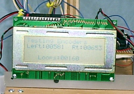
I mated some wheel encoders I purchased from Robotics Connection. to my homemade lexan wheels. You don't really need wheel encoders to do linefollowing, but I wanted to play around with them. Maybe my bot will do other things besides just follow a line.
I develop the code for the microprocessor using Linux and the avr-gcc tool chain and the Atmel AVR ISP serial port programmer. I am pretty sure this source code is compatible with WinAVR, but I don't know for sure (if you try it out, drop me a line and let me know.)
Here's some example C code that sets OC1A to 2KHz PWM to control the motors (someone on the AHRC list asked how to do this on an ATMEGA32):
This zip file has some sample C code for the ATMEGA162 with a 4 MHz crystal for:
This Embedded Systems article byTim Wescott explains how to program a PID motor control loop and includes sample code.
To control the motors, I'm attempting to use locked anti-phase PWM so that it only takes 1 PWM output to run the H Bridge.
Here is what Dale had to say when asked about locked anti-phase PWM. (No, it has nothing to do with flux capacitors or dilithium crystals.)
  First of all, the PWM signal is applied to the DIRECTION  input
  to the H-Bridge. ie: It changes polarity of the motor voltage at the
  PWM frequency.  So you ask, why doesn't the motor draw max current and burn
  up even when stopped?  Winding inductance.  You have to use a high enough
  frequency so the winding appears as a high impedance or put an inductor
  in  series with the motor.  There will be a small current when speed is
  zero depending on the PWM frequency and inductance.

  The motor only responds the the AVERAGE DC voltage. ie: if the power
  supply is 10 volts and the PWM is 50% duty cycle the motor sees an
  average DC voltage of 0.0 volts.  That's +10 for half the time and -10
  for the other half.  In  fact, it sees a virtual short across it's
  terminals - you get breaking  for free.  With 10 volts and a 75% duty
  cycle the motor sees +10 for 75%  and -10 for 25% .  The average is +5
  volts and the motor runs at half speed.

  In locked antiphase the PWM duty cycles are for various speeds are:


  0% pwm = 100% reverse
  25% pwm = 50% reverse
  50% pwm = zero - stopped
  75% pwm = 50% forward
  100% pwm = 100% forward

  Hope that helps.
Tnanks Dale, that helped a lot! Unfortunately, the H Bridge chip I am using doesn't have a direction input. It has 4 separate half H Bridge circuits on it. What I did was to build an inverter so that the PWM signal drives one of the half H Bridge 'A' ports directly, and the second half H Bridge gets the inverted signal. Works just fine on the breadboard!
| Qty | Description | Source | Approx. Cost USD |
|---|---|---|---|
| 2 | R/C Wheels | Hobby Town USA | $3.50 |
| 1 | Lite Flite tail wheel | Hobby Town USA | $4.00 |
| 2 | Tamiya High Power Gear kits | Hobby Town USA | $24.00 |
| 1 | 4"x9" Lexan Sheet | All Electronics | $4.00 |
| 1 | Atmel ATMEGA162 MCU | Digikey | $7.00 |
| 1 | TI SN75441 HBridge IC | Glitchbuster | $1.97 |
| 1 | Perf Board | coldfusionx seller on eBay | $4.00 |
| 2 | Battery Cases | Jameco | $3.00 |
| 1 | Luan Board | Home Depot | $3.00 |
| 2 | Wheel Encoders | Robotics Connection | $24.95 |
| Misc | $20.00 | ||
| Approximate Total | $100.00 | ||

