


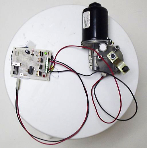
This is a small project for running a wiper motor a low speed. The HBridge schematic using N channel and P channel MOSFETS is a modification of Eugene Blanchard's N & P Channel MOSFET Single Supply HBridge.
Okay, it is hardly a modification at all, it is a direct copy.
My first attempt used all N-Channel MOSFETS, but didn't work and the MOSFETS got hot rather quickly. I hooked up a red and green LED to indicate when the H bridge was on and in what direction. The LEDs would light for a few seconds, then fade out as the MOSFETs got hot. I was told that you needed a source voltage for the gates that was at least 10V higher than the source you were trying to turn on.
Dale Heatherington offered up his advice that I modify the Invertabot HBridge. I eliminated the current sensing stuff and modified it for 12V by moving some resistors.
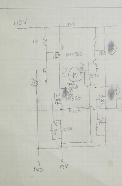
What? You can't read it? See Dale's page for a real schematic, or visit Eugene Blanchard's page above.
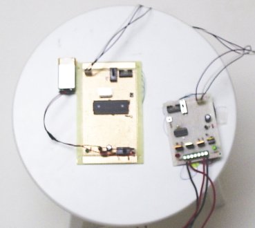
Originally, I was planning to control the motors with a PIC 16F684, which is a 14 pin component that has 4 PWM channels - just the thing for an H-Bridge. Unfortunately, the PP06 programmer didn't recognize it. I switched to a 16F877A. Yes a 40 pin package and all its capabilities makes it overkill for this project, but I had 3 free samples lying around. So I built a second controller board to interface with the board with the 16F684 I had already built.
This most recent attempt acted rather dramatically when I hooked everything together. At first, I hooked a little 9V battery up. It got hot just running the motor for a few seconds. Now, I'm using the 12V battery back from my cordless drill as the power source for the motor. There was a loud PoP!. I saw sparks around where the MOSFETS are, and that gut wrenching smell of burning plastic filled the room.
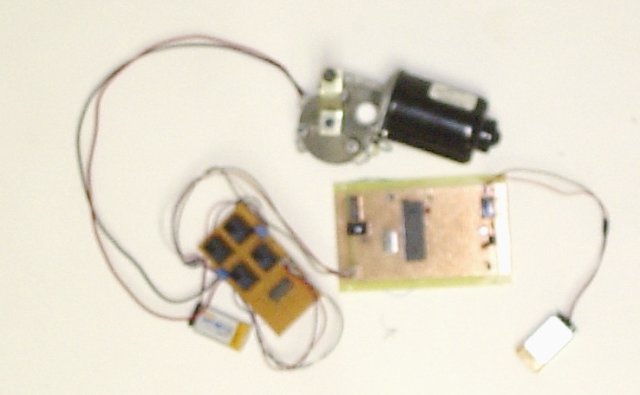
I wimped out on getting the MOSFET circuit to work and created an H bridge out of relays. That went pretty smoothly. It will work perfectly well for this application, but won't be any good for PWM! My 16F877 circuit was acting flaky. Then I found a tiny solder bridge between the OSC1 pin and ground. Scratching that away solved that problem.
I'd better start working on the mechanical part of this if I want it all to work for Halloween (just 3 days away!)
I brought the MOSFET Hbridge to the AHRC meeting. Dale says he thinks there was a source-drain short on one of the MOSFETs.
My relay based HBridge was all working and then... it stopped working (microcontroller problem) so I gave up for Halloween 2004. The project has collected dust until now.
Ok, almost a year has passed. I finally got it to work.
The fireworks from my previous experiment has discouraged me from taking it much further, so before I started on this, I went to Fry's and bought a nice BK regulated (current limiting) power supply. I don't think I would have ever been able to get it to work without it.
I decided I would go with the Eugene Blanchard design. It was fairly simple and exactly what I wanted. I created another point-point prototype. I used an AT-TINY26 since I'm now hooked on the Atmel chips (I like using GCC because it feels so familiar.) And lo and behold, I got it working! For about 30 minutes my motor was going forward and backwards. Then it stopped working for some reason.
So, I whipped up the schematic in Eagle and did a 2 layer board layout with an ATTINY26. I used the old toner transfer method and FeCl to etch the board. It came out O.K. Only 2 traces were completely obliterated.
The new power supply was a life saver. Here I had everything worked out, but that 'current limited' led was lighting up quite a bit. One of the N-Channel MOSFETs was getting quite warm. Finally I figured out that I had put in all 4 of the transistors backwards. Then, I figured out that one of the diodes was in backwards too. Now its all working.
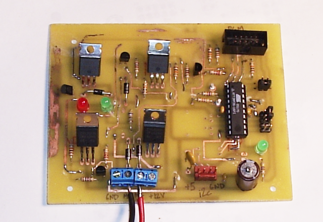
Front
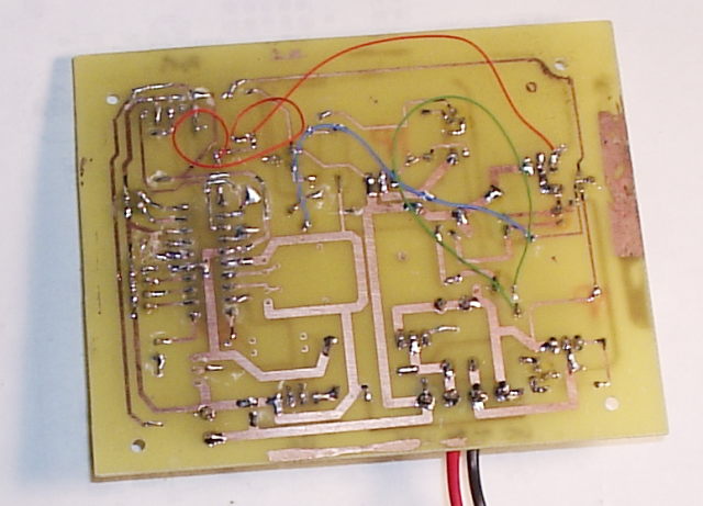
Back
The next step is to test out the PWM, which I've never done before. I have designed the circuit to accommodate a rotary encoder, and to accept I2C input from another microprocessor.

