


<<< Back to Eric's Halloween projects

This project is used to control a set of LEDs that are put in candles in order to made an interesting halloween display. The controller that lights up the candles also has a proximity sensor connected in order to start a scary sequence with the candles dimming and then activating an animated spooky figure.
The project is based on a Parallax Inc. app note You can download a .pdf file from them with more details and sample code written in BASIC for the BASIC stamp. Mike Lynch of AHRC passed it along to me.
Our house has a driveway leading to a sidewalk that is kind of hidden behind some bushes. Behind the bushes is where I want to setup the spooky stuff.
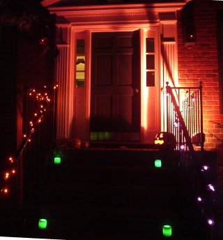
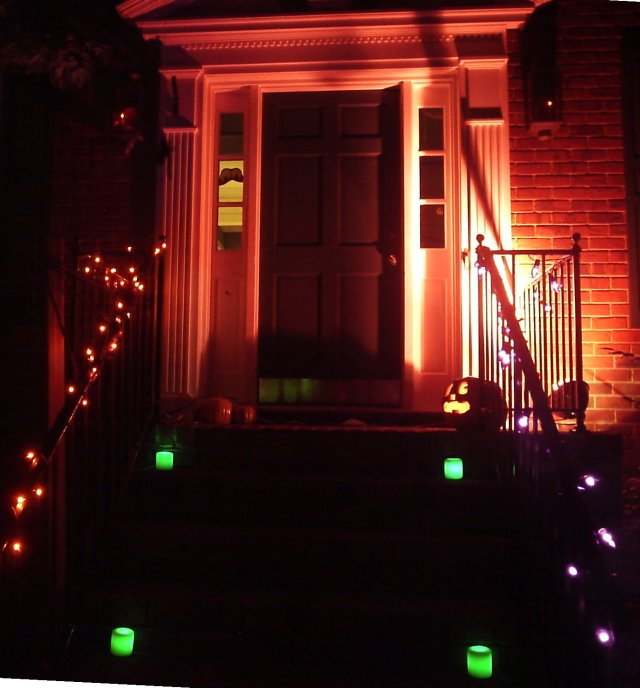
The candles on Halloween night 2005 sitting on the front stoop Larger Image
The appnote calls for a BASIC stamp based controller. Since my current preferred architecture is Atmel AVR chips programmed with 'C', I decided to implement with the ATTINY26. I also had lots of very bright green LEDs that Steve Karg of AHRC brought to a meeting a few months ago. These LEDs are very bright and intended for daylight use. I also had a few ULN2003 ICs from Glitchbuster and a 900ma 7V wall power supply lying around.
I wired in a Sharp proximity sensor from the Mark III robot store to start the spooky flashing sequence and a little 315 MHz remote control transmitter from ColdfusionX on eBay. to trigger the spook (which is running on a rope with no wires attached.)
This project went together really quickly, but then its about the 3rd board I have made with the ATTINY26 so I was familiar with it.
The candles are supposed to be drilled into in order to put the LEDs in. In the appnote, they drilled all the way through the candle and the LED is right near the top. I didn't want to see the LED when you looked down, so the first candle we used I drilled into the bottom just a bit and put the LED in the middle of the candle. It had a very nice diffusing effect, as the candle was translucent. Since we needed more, we picked up 2 cheap white candles at Target and I cut them in half. These candles were not translucent, so I had to drill them all the way through. It has a different effect, but still looks cool.
I used these high intensity green LEDs because I had them on hand. These high intensity LEDs can hurt your eyes if you look straight at them for a long time, so I tried to keep them buried in the candle
We tried lighting the first translucent candle with the LED on. The candle was much brighter than the LED, but you could still (barely) see a tinge of green at the bottom.
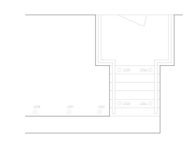
The following files show the design and some test routines for programming the ATTINY26. I have included some extra parts of the schematic that aren't necessary that I included on my setup (reset push button, debug LED, external remote control output, and programming header.)

